
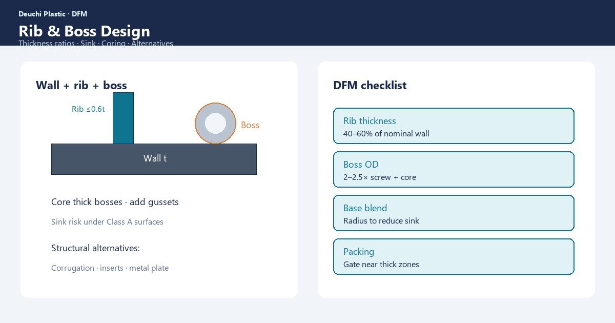
Ribs and bosses turn flat panels into stiff, attachable structures — and they are the most common source of sink marks on show faces. Over-thick ribs feel “strong” in CAD and fail cosmetics at T1. Under-designed bosses crack under screws. Getting rib and boss design injection molding right is a DFM discipline: thickness ratios, height limits, coring, and structural alternatives before steel.
Procurement feels bad rib design as sink scrap, endless hold-pressure trials, and steel changes after texture. Designers feel it as a conflict between FEA stiffness and appearance. Quality teams feel it as undefined cosmetic depth over features that drawings never flagged as sink risks.
This guide covers rib height and thickness rules, boss design, coring, sink linkage, structural alternatives, and a DFM table for RFQs. Review features with the DFM review checklist before locking production CAD.
Rib thickness and height — rules that prevent sink
For many unfilled amorphous resins, rib thickness should stay about 50–60% of the adjacent nominal wall. Semi-crystalline and filled grades may need tighter ratios. Rib height is often limited to roughly three times the nominal wall for practical molding and draft, though structural needs vary — taller ribs need draft, venting, and fill capability.
| Rib parameter | Typical starting rule | If violated |
|---|---|---|
| Thickness vs wall | ~50–60% of nominal wall | Sink on show face |
| Height | Often ≤ ~3× wall (application-dependent) | Fill, draft, eject issues |
| Base radius | Modest blend; avoid heavy mass | Local sink / stress |
| Spacing | Enough for steel strength and cooling | Hot steel, warp, weak tool |
- Keep ribs thinner than the wall they reinforce
- Add draft to rib sidewalls for release
- Align ribs with flow when possible to aid packing
- Avoid intersecting thick rib grids that create solid nodes
- Vent deep rib tips to prevent burns and shorts
Sink physics and pack/hold limits are covered alongside this topic; treat rib ratio as primary prevention in DFM.
Boss design for screws, inserts, and loads
Bosses concentrate mass. Solid bosses behind Class A faces are classic sink generators. Design bosses as thin-walled tubes with cores, connected to walls or ribs with gussets rather than heavy fillets that recreate bulk.
- Core bosses; target wall thickness compatible with adjacent walls
- Use gussets for strength instead of thick cylinders
- Stand bosses off show faces when cosmetics matter
- Design for self-tapping screws or inserts with correct ID/OD and depth
- Watch knit lines around cores — strength and cracks at screw bosses
Insert molding and screw retention add their own DFM rules; gate and weld placement around bosses belongs in the mold concept — see OEM mold design guide.
Coring out mass — the cheapest sink fix
Coring removes volumetric shrink drivers. Core thick rims, mounting blocks, and logo pads. Maintain steel strength and cooling access — aggressive coring that leaves fragile cores or uncoolable steel creates warp and maintenance pain.
| Feature | Coring approach | Watch-outs |
|---|---|---|
| Mounting block | Honeycomb / pocket cores | Steel strength; eject |
| Boss | Blind core; gusset to wall | Knit line; screw depth |
| Thick rim | Channel core; keep wall uniform | Warp if asymmetric |
| Raised logo | Reduce height; recess art | Cosmetic Class |
Coring decisions interact with cooling layout in mold build. Uncooled thick steel opposite a cored part can still warp — see warpage causes and prevention.
Sink risk link — design vs process
If sink tracks rib and boss locations exactly, geometry dominates. Process hold can reduce visibility within a window; it will not erase an over-thick rib under deep Class A texture. Define acceptance criteria (lighting, depth, zones) before T1 arguments.
- Map every rib/boss under cosmetic faces in DFM
- Flag features that violate thickness ratios for redesign
- Only then run pack/hold DOE for residual marks
- Escalate to steel/CAD when no capable window exists
Capture cosmetic CTQs over features in first article inspection.
Structural alternatives when ribs would mark
When stiffness needs exceed cosmetic-safe rib ratios, change the architecture:
- Increase nominal wall carefully (watch sink/cycle) or use curvature for stiffness
- Move ribs to non-show interiors; use two-shot or assembly covers
- Use metal brackets or inserts for local loads instead of plastic mass
- Select higher-modulus grades only with weld and warp DFM (fillers change shrink)
- Split parts so structural and cosmetic functions separate
Soft-tool FEA correlation may not match production anisotropy — use the prototype-to-production roadmap when structural CTQs matter.
DFM table for RFQ packages
| Check item | Pass criteria | Owner |
|---|---|---|
| Rib thickness ratio | Within material guideline vs wall | Design + DFM |
| Boss coring | No solid bosses under Class A | Design |
| Draft on ribs/bosses | Per pull direction and texture | Design + tooling |
| Gate packing path | Can feed thick features | Tooling |
| Weld at screw bosses | Not in high-stress plane if avoidable | Tooling + CAE |
| Cosmetic sink criteria | Written lighting/depth rules | Quality |
| Cooling near ribs | Channels reachable | Mold design |
Attach section cuts of critical ribs and bosses to the RFQ so suppliers quote cooling and gate intent correctly.
During DFM walkthroughs, color-code ribs that sit behind Class A faces versus interior-only ribs. Prioritize ratio compliance on show-critical features first, then optimize interior structure for stiffness and molding. That triage prevents polishing a tool around features that were never cosmetic-safe. Also confirm screw boss depths against fastener specs — over-deep solid bosses recreate sink even when OD walls look thin on a single section cut.
If FEA demands more stiffness after DFM thins ribs, revisit architecture with manufacturing in the room: add curvature, split the part, or move load into metal. Iterating thickness upward in isolation is how programs rediscover sink after texture.
For screw bosses, publish a fastener schedule with hole size, engagement depth, and expected clamp load. Molding suppliers cannot judge boss OD and coring without that data, and overbuilt bosses are the usual compromise when the schedule is missing. Include boss sections in every RFQ package alongside the wall map so sink and strength are quoted as one problem. Update that package whenever fastener or insert specs change mid-program.
How Deuchi approaches rib and boss DFM
Deuchi reviews rib ratios, boss coring, and show-face sink risk before production steel. Structural needs are met with gussets and architecture — not solid mass behind Class A panels.
Contract manufacturing programs define sink acceptance over features and verify packing paths at T0/T1. That shortens cosmetic loops and protects launch timing when rib-heavy housings move from prototype intent into production steel.
FAQ
Can I use 70–80% wall thickness ribs if the part is structural?
You can, but expect sink risk on opposing faces. Prefer redesign, non-show ribs, or acceptance criteria changes rather than hoping process hides thick ribs on Class A.
Do glass-filled resins allow thicker ribs?
Fillers often reduce sink magnitude but add weld and warp complexity. Do not thicken ribs casually — revisit the full DFM set.
How close can ribs be spaced?
Leave enough steel for strength, polishing, and cooling. Over-dense rib forests create hot molds and ejection problems even if plastic ratios look fine.
Should bosses always have gussets?
Gussets usually improve strength without solid mass, but poorly designed gussets can create their own sink. Keep gusset thickness in ratio and avoid heavy junctions.
Next step
Share wall sections, rib/boss cuts, and cosmetic Class maps for a rib-and-boss DFM review. Contact Deuchi at https://deuchiplastic.com/contact/ to align design rules, sink criteria, and mold concepts before cutting steel.