
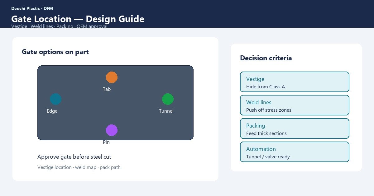
Gate location decides fill path, packing into thick sections, weld-line maps, and where a vestige will sit for the life of the product. Changing a gate after texture and polish is among the most expensive mold revisions an OEM can buy. Getting gate location injection molding right is an approval workflow before steel — not a tryout afterthought.
Procurement feels late gate moves as schedule hits and steel weld risk. Designers feel them as cosmetic vestige versus structural knit trade-offs. Process engineers feel them as pressure drop and freeze-off that no hold profile can fully repair if the gate cannot feed the thick zone.
This guide summarizes common gate types, cosmetic vestige, weld placement, packing strategy, and an OEM approval path before cutting cavities. Use it with the DFM review checklist and your mold concept package.
Gate types — what buyers should recognize
Gate type constrains where you can place the feed and what vestige remains. Selection is material-, cosmetic-, and automation-dependent.
| Gate type | Typical use | Buyer notes |
|---|---|---|
| Edge / tab | Simple parts, cold runner | Visible edge vestige; easy to tune |
| Submarine / tunnel | Auto-degating | Vestige on non-show; shear heating |
| Pin / pinpoint | 3-plate cold runner | Small vestige; freeze behavior |
| Hot tip / sprue | Hot runner center feed | Excellent packing path; vestige/mark |
| Valve gate | Sequential multi-gate | Weld control; higher tool cost |
| Fan / film | Wide thin sections | Cosmetic distribution; trim needs |
Hot versus cold runner choices affect balance, color change, and vestige — discuss in mold build quoting, not after PO. Details belong in the OEM injection mold design guide review.
Cosmetic vestige — plan the scar
Every gate leaves evidence: a nub, witness, blush, or shear mark. Class A strategy is to place the vestige where customers will not see it, where a label covers it, or where secondary trim is planned and costed.
- Mark forbidden vestige zones on cosmetic Class drawings
- Decide trim method (manual, robot, in-mold degate) and residual height
- Account for blush or jetting risk on show faces near gates
- For living hinges, never sacrifice cross-hinge flow for a prettier vestige without life testing
Ambiguous “gate OK anywhere non-show” language fails when assembly covers move in later revisions. Freeze vestige locations with product design sign-off.
Weld lines and flow path from the gate
Gate location sets how flow splits around holes and where fronts rejoin. Multi-gate layouts create joins between gates; single gates create joins mainly around obstacles. Sequential valve gates can push welds into safer zones.
- Overlay predicted welds on cosmetic and structural maps
- Forbid welds on living hinges, sealing lands, and high-stress ribs
- Use gate count for fill capability, then relocate to park welds
- Validate imbalance risk on multi-cavity tools — wandering welds are a quality escape
Weld-line physics and Class A relocation tactics are covered in depth alongside this topic; treat gate and weld as one decision set in DFM.
Packing into thick sections and sink control
Gates must remain open long enough and transmit pressure into thick bosses and rims. A tunnel gate that freezes early can fill the cavity yet leave sinks over thick features. Center hot tips often pack well but may put vestige on a show face unless designed carefully.
| Packing goal | Gate implication | Risk if wrong |
|---|---|---|
| Feed thick boss | Gate near or path toward boss | Sink / void far from gate |
| Uniform density | Balanced multi-gate or good single path | Warp, dimensional bias |
| Thin-wall fill | Larger/faster gate; hot runner | Short shot, hesitation |
| Fiber orientation | Gate sets anisotropy map | Warp / weak axis |
Sink and warpage share packing-path roots — see warpage causes and prevention when flatness CTQs exist. Do not approve gate locations that cannot pack CTQ thick zones.
OEM approval workflow before steel
Make gate approval a gated milestone:
- DFM — wall map, cosmetic Class, weld forbidden zones, hinge rules
- Gate concept — type, location, vestige, runner/hot drop sketch
- Simulation review — fill, weld, pressure; treat as risk ranking
- Cross-functional sign-off — design, quality, tooling, manufacturing
- Steel release — only after written approval of gate package
- T0/T1 — verify welds, vestige, sink; change control if gate move needed
Capture vestige and weld CTQs in first article inspection. Soft-tool gates may differ — correlate with the prototype-to-production roadmap.
| Approval artifact | Must include |
|---|---|
| Gate layout drawing | Locations, types, vestige callouts |
| Cosmetic Class overlay | Forbidden vestige/weld zones |
| Process intent note | Packing targets for thick CTQs |
| Change control | Who can move gates after steel |
Family molds and multi-cavity tools add another layer: gate sizes must balance fill so weld maps and packing do not differ cavity-to-cavity. A gate that works on cavity one but shorts cavity four is not an approved layout. Require balance data at T0 and freeze valve timing or cold-runner dimensions under change control.
When product design later adds a hole, logo, or living hinge near an approved gate path, reopen the gate package. Silent CAD edits are a common root cause of “new” weld lines on tools that previously passed FAI. Tie ECO review to gate and weld overlays so manufacturing sees the flow impact before steel is touched.
Buyers should also ask how the gate will be sampled in production: automatic degating consistency, vestige height SPC, and criteria for tip residue or blush. A gate that looks acceptable on ten T1 shots can drift when tips wear, valve pins stick, or operators change trim methods. Put vestige metrology on the control plan for Class A parts, not only on the FAI checklist.
Finally, align gate decisions with material drying and color strategy. Hot tips and submarine gates behave differently with shear-sensitive colors and flame-retardant grades. If a late color or FR change is likely, stress-test the gate concept for jetting and freeze-off before locking steel — cheaper than discovering a packing limit after polish. Record the approved resin, colorant package, and gate layout on one controlled document so substitutions cannot silently break the packing path.
How Deuchi approaches gate location decisions
Deuchi treats gate location as a DFM deliverable with written OEM sign-off before production steel. We balance vestige, weld placement, and packing paths in one review so tryout does not rediscover conflicts.
Contract manufacturing programs document gate approval artifacts and FAI cosmetic methods. That reduces late steel changes when multi-gate or hot-runner tools are involved. Clear ownership of vestige and weld CTQs keeps design, tooling, and quality aligned from DFM through production release.
FAQ
Should we always gate into the thickest section?
Often preferred for packing, but cosmetics and welds may forbid it. If you cannot gate into thickness, core the mass or accept sink criteria. Do not assume process will compensate forever.
When are valve gates worth the cost?
Large Class A parts, weld relocation needs, or family molds with fill balance challenges. Cost is justified when weld or flash risk would otherwise force steel iteration.
Can we move a gate after T1 if vestige is ugly?
Possible but expensive — welding, re-machining, re-texture, re-polish, and requalification. Prevent with vestige sign-off before steel.
Do simulation results freeze the gate location?
No — they rank risk. Freeze location with cross-functional approval, then confirm at tryout. Update the approved package if steel changes.
Next step
Share CAD, cosmetic Class maps, and preferred vestige zones for a gate-location DFM review before steel. Contact Deuchi at https://deuchiplastic.com/contact/ to align gate type, weld placement, and packing strategy for your next mold program.