
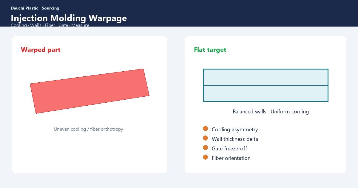
Flat lids that rock on a granite table and long walls that bow after cooling are classic injection molding warpage failures. Scrap piles grow when teams argue “process vs design” without a measurement method or a ranked cause list. Warpage is differential shrinkage made visible — cooling, wall geometry, fiber orientation, and gate strategy are the usual drivers.
Procurement teams feel warpage as late-stage cost: endless T1 loops, rejected assembly fits, and air-freighted “urgency samples” that still fail flatness CTQs. Industrial designers feel it as seams that no longer meet. Quality teams feel it as dimensional drift across a week of production when cooling fouls.
This guide ranks common causes, DFM prevention practices, measurement approaches, and a decision frame for when to fight with process versus when to change design or steel.
Warpage is differential shrink — diagnose before you tweak
Plastic shrinks as it cools from melt to solid. If one region freezes earlier or orients differently than another, residual stress twists the part. Generic “increase pack” without knowing which mechanism dominates wastes weeks.
- Cooling imbalance — hot vs cold steel regions lock in different shrink
- Wall thickness variation — thick sections shrink more and pull thin sections
- Fiber orientation — glass-filled resins shrink differently along vs across flow
- Gate and packing — late packing and knit zones change density distribution
- Ejection and fixturing — mechanical distortion after demold can masquerade as warp
Start with a hypothesis, then measure. Our DFM checklist forces wall and gate risk discussion before steel — cheaper than living with warp for the tool’s life.
Distinguish molded warp from assembly-induced distortion. Clamping lids onto warped bases, ultrasonic welding while parts are still warm, or packing soft stacks for ocean freight can reshape plastics after demold. Record when and how parts are measured relative to shipping and assembly — otherwise suppliers and buyers will argue the wrong root cause.
Cause set 1: cooling design and maintenance
Under-cooled cores or asymmetric channel layouts create persistent temperature maps in steel. Flat enclosure lids and large trays are especially sensitive. Even a well-designed cooling circuit fails when scale, oil films, or plugged baffles break heat removal mid-campaign.
| Cooling symptom | Likely effect | First check |
|---|---|---|
| One side of tool hotter | Bow toward cooler side patterns | Thermal imaging or surface probes |
| Long cycle but still warp | Channels too far from thick zones | Cooling layout vs wall map |
| Warp worsens week-to-week | Fouling / flow restriction | Flush circuits; verify flow rates |
| Hot spots near shut-offs | Local densification differences | Baffles, bubblers, inserts |
Ask for cooling concepts on warp-critical parts in mold build quotes. Cooling is process capital, not a detail.
Specify water temperature and flow monitoring when flatness is a CTQ. Plants that only check “water is on” miss channel restrictions that create weekly drift. Flow meters and periodic thermal checks belong on the process control plan for large lids and trays.
Cause set 2: wall geometry and bosses
Thick bosses behind Class A faces sink and pull. Ribs that are too thick relative to adjacent walls create differential shrink. Abrupt thin-to-thick transitions freeze unevenly. Warpage here is primarily design — process can only mask within a window.
- Target uniform walls; transition gradually where function forces change
- Keep rib thickness roughly compatible with adjacent walls (material-dependent ratios)
- Core out mass; avoid solid blocks under flat panels
- Balance features across a centerline when possible
- Use correlating gussets carefully — they can also create shrink pull
Resolve these in DFM before multi-cavity steel. Redesigning after texture and polish is expensive.
Cause set 3: fiber-filled materials and gate orientation
Glass- or carbon-fiber resins shrink less along fiber direction than across. Gate location and flow length therefore set anisotropy patterns. Multiple gates create weld and orientation maps that can bow long parts predictably — or unpredictably if gates are unbalanced.
| Material behavior | Design / tooling response |
|---|---|
| High fiber anisotropy | Simulate orientation; place gates for symmetry |
| Long thin walls | Prefer flow direction that reduces across-flow shrink in CTQ axis |
| Weld lines in stress areas | Move gates; add overflow or redesign ribs |
| Thin skins over thick bosses | Core bosses; reconsider fiber grade vs unfilled |
Do not “fix” anisotropy solely with pack pressure. Orientation is flow physics. Gate strategy belongs in early DFM, especially for structural housings and gear carriers.
Cause set 4: packing, hold, and process windows
Insufficient hold time or pressure leaves thickness gradients of density. Excess pack can flash or overpack near gates, making near-gate regions denser than far-gate zones — another warp driver. Material moisture and melt temperature also change shrink magnitude.
- Establish a documented process window with DOE when CTQs are tight
- Separate short-shot filling issues from packing-driven dimensional bias
- Dry hygroscopic resins to spec — wet resin changes shrink and cosmetics
- Validate cavity-to-cavity balance on multi-cavity molds
Process ownership should appear in production work instructions so operators do not “chase” warp with unrecorded knob turns.
Measuring warpage without ambiguous arguments
Define datums and measurement method before arguing suppliers. Flatness on a surface plate with feeler gauges, CMM profiles, optical scans, or dedicated fixtures — pick one and keep it. Photograph fixtures and record temperature soak conditions for plastic parts that stabilize slowly.
- Specify CTQ: flatness, parallelism, or gap to mating part
- Define measurement fixture and clamp state (free vs constrained)
- Record part age and ambient conditions after demold
- Sample across cavities and shot sequence
- Correlate to process data and steel temperatures when unstable
FAI should capture warp CTQs explicitly — see first article inspection guide.
When to change process vs design vs steel
| Evidence | Prefer action |
|---|---|
| Warp moves with cooling fouling / week drift | Maintenance + cooling verification |
| Warp stable; thick-thin geometry obvious | Design change (walls/bosses) |
| Fiber grade; bow follows flow direction | Gate/orientation change or material rethink |
| Only one cavity warps on multi-cavity | Balance/steel cooling per cavity |
| Process DOE shows no capable window | Steel/cooling redesign — process exhausted |
Do not burn launch calendar iterating process forever when geometry makes capability impossible. Escalate to design or mold revision with data. Program buffers: lead time planning.
How Deuchi approaches warp-critical parts
Deuchi emphasizes wall uniformity, gate concepts, and cooling intent in DFM before committing production steel. For enclosure lids and long housings, we treat flatness CTQs as mold-design drivers — not afterthought process knobs.
Contract manufacturing programs include measurement definition for warp CTQs so T1 acceptance criteria are unambiguous. That reduces circular arguments and speeds containment when drift appears.
FAQ
Can annealing or fixtures fix warpage after molding?
Sometimes as containment for specific materials/geometries — not as a substitute for cooling and wall design. Fixturing adds labor and can mask dimensional true state if not controlled.
Does glass fill always increase warpage?
It changes the warp mode (anisotropy) more than it universally “increases” warp. Unfilled amorphous resins can also bow severely from cooling imbalance. Match diagnosis to material class.
Why did soft-tool parts look fine but steel production warp?
Aluminum soft tools cool differently, cycles differ, and gates may change. Soft-tool samples inform fit — they do not guarantee production anisotropy or cooling maps. Correlate intentionally — see prototype-to-production roadmap.
Should we demand mold-flow analysis for every part?
Prioritize for warp-critical, fiber-filled, or large flat geometries. Analysis is a decision aid — still verify with measured T0/T1 and steel temperature data.
Next step: Contact Deuchi with CAD, flatness or gap CTQs, and material grade — request DFM focused on warp risk before steel cut.