
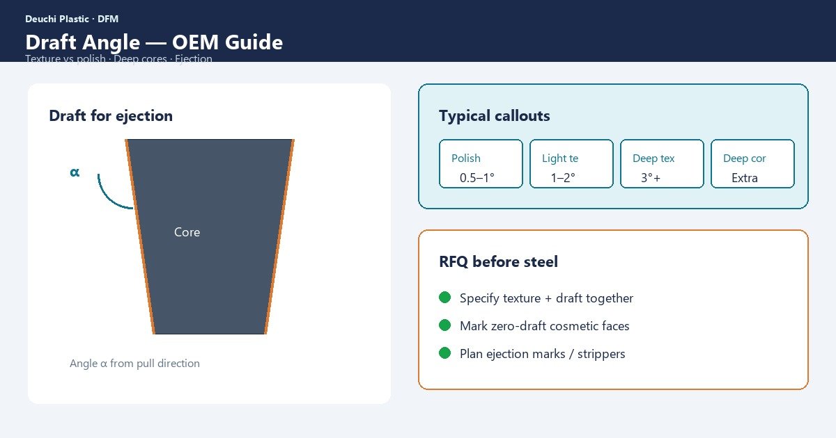
Parts that stick, score, or white-stress on ejection usually share a root cause: insufficient draft on deep walls, cores, or textured faces. Draft is not a cosmetic preference — it is how steel releases plastic without fighting friction and vacuum. Specifying draft angle injection molding correctly in the RFQ prevents tool rework, ejection marks, and “zero draft” CAD that looks fine on screen and fails at T0.
Procurement feels missing draft as steel welding, extended tryout, and scrap from drag marks on Class A walls. Designers feel it as a conflict with vertical styling lines. Quality teams feel it as intermittent scoring when texture depth, polish, and ejection force interact.
This guide explains why draft matters, textured versus polished rules of thumb, deep core risks, ejection marks, when zero draft fails, and how to call draft out in RFQs. Pair it with the DFM review checklist before cavity steel.
Why draft exists — friction, shrink, and vacuum
As plastic cools it shrinks onto cores and male features. Without draft, contact pressure rises and ejection force spikes. Texture increases the effective interference because peaks dig into the polymer. Deep boxes create vacuum effects if air cannot re-enter behind the part. The result is drag lines, stress whitening, cracked bosses, and bent ejector pins.
- Shrink onto cores — male features need more draft attention than open cavities in many cases
- Texture and polish — deeper texture needs more draft than fine polish
- Depth — taller walls multiply friction length
- Material stickiness — soft TPEs and some sticky grades need extra draft/release
Resolve draft in DFM while styling can still flex. Changing draft after texture is expensive steel work.
Textured vs polished — practical draft rules of thumb
Rules of thumb are starting points, not laws. Material, depth, and ejection design change requirements. Still, OEMs need defaults for early CAD:
| Surface condition | Typical draft starting point | Notes |
|---|---|---|
| SPI A fine polish, shallow wall | ~0.5–1° per side | May need more on deep cores |
| SPI B / light texture | ~1–2° per side | Confirm with texture depth |
| Medium–deep texture (VDI / MT) | ~1° per 0.001 in texture depth (common rule of thumb) or ≥3°+ | Supplier-specific; validate |
| Soft / sticky materials | Extra draft + release aids | Do not copy rigid resin draft |
Always state draft relative to the pull direction and whether it is per side. Ambiguous “2° draft” without pull direction causes CAD and mold disagreements. Align finish Class with draft using SPI finish expectations on the drawing.
Deep cores, shut-offs, and ejection marks
Deep cores magnify shrink lock. Inadequate draft shows as vertical drag, glossy burnish strips, or whitening. Over-aggressive ejection (too few pins, pins in soft zones, early ejection while hot) creates circular pin marks that buyers confuse with design defects.
- Apply draft to both cavity and core faces as required by geometry
- Add draft to ribs, bosses, and logo sidewalls — not only outer shells
- Design ejector layout for balanced push; avoid tiny pins on Class A
- Consider air poppets or stripper plates for deep cups
- Plan texture direction and polish so drag is minimized if slight scuff occurs
Ejection strategy belongs in mold build concepts, not only in process tryout. Process can reduce stick with mold temperature and release agents; it cannot invent draft that CAD omitted.
When zero draft fails — and rare exceptions
Zero draft CAD is a common styling ask. It fails when:
- Walls are deep enough for shrink lock and drag
- Texture is present on the vertical face
- Material is soft, sticky, or high-shrink
- Ejection access is limited (no stripper, few pins)
Exceptions exist for very shallow features, some open trays with excellent release, or designs using lifters/slides that change pull direction. Treat exceptions as engineered decisions with tryout risk accepted in writing — not as default CAD hygiene.
| Situation | Risk if zero draft | Better approach |
|---|---|---|
| Deep textured enclosure | Severe drag / scrape | Add draft; hide with styling break |
| Shallow logo pad | Often manageable | Confirm depth and polish |
| TPE overmold wall | Stick and tear | Extra draft; release; geometry |
| Optical lens sidewall | Marking / haze | Draft + polish plan; careful eject |
Draft conflicts with warpage and sink when designers thicken walls to “hide” draft visually — keep walls uniform and use styling breaks instead. See warpage causes and prevention.
RFQ and drawing callouts that prevent arguments
Put draft in the RFQ package so quotes assume the same steel:
- Pull direction clearly defined on the drawing
- Minimum draft by surface Class (A/B/C) and by texture specification
- Draft on ribs, bosses, cores, and shut-off walls called out explicitly
- Allowed exceptions listed with owner approval
- Ejection mark zones and forbidden Class A pin locations
Reference the OEM injection mold design guide expectations in supplier kickoffs. Capture ejection cosmetics in first article inspection under agreed lighting. Soft-tool release may differ from textured steel — correlate via the prototype-to-production roadmap.
At T0, photograph drag lines relative to pull direction, note whether marks worsen as the tool heats, and record ejection delay and mold temperature. If marks clear only with excessive spray or delayed eject, treat that as evidence of insufficient draft or weak ejection design — not as a sustainable process. Buyers should require a written containment plan and a steel or CAD corrective action when cosmetics depend on operator heroics.
Also verify rib and boss sidewalls received draft in CAM, not only the outer shell. Many tryout failures come from internal features modeled vertically for FEA convenience. A quick draft analysis color map before steel release catches most of those escapes and protects texture investment on Class A walls.
Procurement should treat “zero draft styling” as a formal exception request with owner, risk, and tryout contingency — not as a silent CAD default. When marketing insists on vertical walls, offer styling breaks, split lines, or slight draft hidden in radii before accepting steel risk. Written exceptions keep accountability clear when T0 marks appear.
How Deuchi approaches draft-critical tools
Deuchi reviews pull direction, texture-draft pairing, and deep core release in DFM before production steel. We call out rib and boss draft explicitly so styling models do not silently omit it.
Contract manufacturing tryouts document ejection force symptoms and cosmetic drag so steel or CAD changes are evidence-based. That keeps Class A launches from discovering draft the hard way after texture.
FAQ
Is 1° draft always enough for polished parts?
Not for deep cores or sticky materials. Use 1° as a starting point for shallow polished walls, then increase with depth and risk. Validate at T0.
Can mold release spray replace draft?
Release agents are process aids and contamination risks for painting or medical parts. They do not replace missing draft on deep textured walls.
Why did aluminum prototype eject fine but steel stick?
Different thermal shrink, surface finish, texture depth, and ejection systems. Prototypes inform risk; production draft must still be designed intentionally.
How should we specify draft with VDI texture?
Call texture standard and depth, then state minimum draft (or draft vs depth rule) on the same drawing. Do not leave draft “per mold maker” without a number.
Next step
Share CAD, pull direction, and texture callouts for a draft-angle DFM review before steel. Contact Deuchi at https://deuchiplastic.com/contact/ to align draft rules, ejection strategy, and cosmetic acceptance for your next mold.