
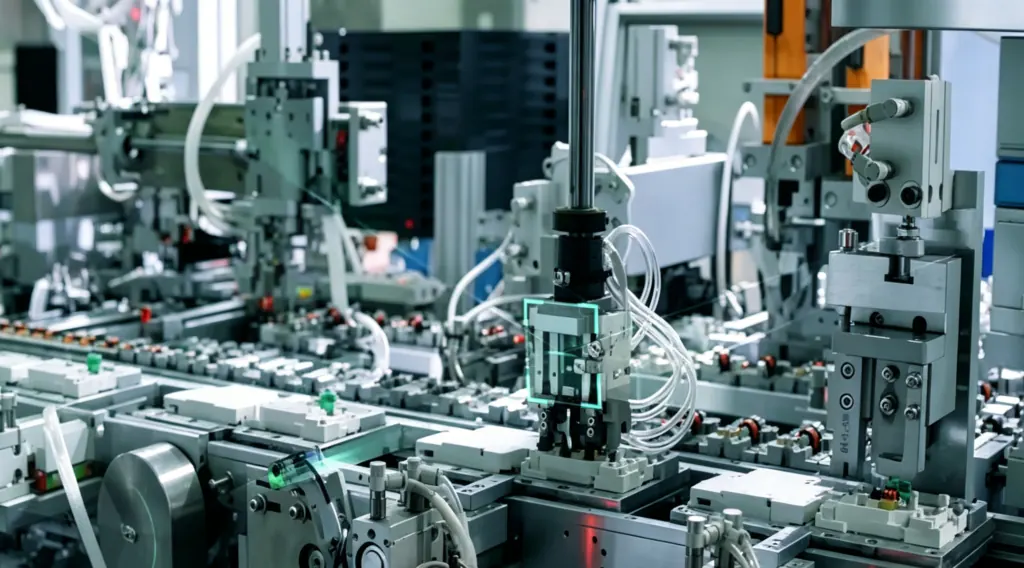
When people say “plastic injection mold parts,” they usually mean production-grade components made by injecting molten polymer into a steel or aluminum mold, then cooling and ejecting the part. You’ll also see the term injection molded plastic parts ” used interchangeably. It’s the default process when you need repeatability, complex 3D geometry, and a unit cost that keeps falling as volumes rise.
For an OEM team early in development, the hard part isn’t understanding the basics of injection molding. It’s figuring out what “type” of part you have, what those types imply for tooling complexity, and which early design choices can quietly turn a simple mold into a complicated one.
What counts as a plastic injection molded part (and why the category matters)
A plastic injection-molded part is defined more by the tooling approach than the application. The same process produces:
housings and covers
clips and latches
gears and bushings
caps and closures
insert-molded parts with metal threads
overmolded parts with soft-touch grips
The “type” matters because it predicts:
whether you can build a straight-pull two-plate mold or need slides/lifters
the cosmetic and dimensional control you can reasonably expect
how sensitive the part is to warpage, sink, and ejection marks
What you should prototype (and how) before you cut steel
A practical taxonomy of plastic injection mold parts (by geometry and features)
There are many ways to categorize molded parts. For early-stage engineering and sourcing discussions, this feature-based taxonomy is the most useful because it maps directly to mold design decisions.
1) Shells and housings (enclosures, covers, bezels)
What they are: two halves of a housing, covers, bezels, or protective shells.
Why injection molding fits: you get consistent wall thickness control, repeatable snap features, and surface finishes that can go straight to assembly.
Early DFM flags:
long flow length vs thin walls (risk of short shots)
large flat surfaces (warp sensitivity)
cosmetic “A-surface” needs (gate and ejector strategy)
If your part is an enclosure, it’s worth separating “the plastic part” from the system requirements (sealing, EMI, flammability) early; those requirements can drive resin choice and wall thickness decisions. For a structured enclosure checklist, see Deuchi Plastic’s guide: RFQ checklist and design considerations for custom plastic electronic enclosures.
2) Thin-wall parts (lightweight containers, lids, cosmetic shells)
What they are: parts where wall thickness is pushed low to reduce material, weight, and cycle time.
Why injection molding fits: high repeatability and high output once the process window is tuned.
Early DFM flags:
fill pressure increases as walls thin
gate location and venting become less forgiving
warpage and sink show up fast when thickness isn’t uniform
⚠️ Warning: “Thin-wall” is less a part category than a process capability. Don’t assume a supplier can run thin-wall just because they can mold the same resin at thicker walls.
3) Snap-fit and latch parts (clips, hooks, living retention features)
What they are: parts that assemble without screws (or features on a housing that act as the fastener).
Why injection molding fits: molded-in assembly features reduce BOM count and assembly time.
Early DFM flags:
local stress concentration at the snap root
dimensional stack-up across mating parts
whether the snap creates an undercut that forces side actions
4) Living hinge parts
What they are: a thin flexing section that acts as a hinge (common in packaging and some industrial covers).
Why injection molding fits: a living hinge is typically a single-piece solution.
Early DFM flags:
hinge geometry must be consistent and well-oriented for flow
resin choice matters (some materials handle repeated flex better than others)
5) Threaded parts and closures (caps, plugs, collars)
What they are: threaded caps/closures and parts with molded threads.
Why injection molding fits: high repeatability on circular geometry, and the cost per part is low at volume.
Early DFM flags:
internal threads may require unscrewing mechanisms or collapsible cores
sealing surfaces and roundness requirements should be explicit
6) Gears, bushings, and wear parts (mechanical transmission)
What they are: gears, bushings, pulleys, sliders, and low-friction components.
Why injection molding fits: net-shape production of complex geometry at scale.
Early DFM flags:
tolerances and runout expectations must match the process capability
resin selection (wear, friction, creep) matters as much as geometry
If material choice is still open, Deuchi Plastic’s comparison of common resins is a practical starting point: Material selection guide for injection molded plastics: ABS, POM, PC, and PP with DFM insights.
7) Insert-molded parts (metal threads, pins, bushings molded in)
What they are: plastic parts molded around a pre-placed metal component.
Why injection molding fits: you get metal’s functional surface (threads, conductivity, wear) with plastic geometry and weight.
Early DFM flags:
insert location and retention during molding
thermal expansion mismatch and stress
quality controls for insert presence/orientation
If your concept needs molded-in metal features, it’s worth understanding the tradeoffs between insert molding and post-assembly options early.
8) Overmolded parts (soft grips, seals, multi-material interfaces)
What they are: two-material parts (e.g., rigid substrate + soft-touch TPE).
Why injection molding fits: combines functions (structure + grip/seal) into one part.
Early DFM flags:
bonding mechanism (chemical vs mechanical lock)
how the first-shot part is located for the second shot
cosmetic transitions and parting line strategy
Overmolding is one of several types of injection molding that trades tooling/process complexity for integrated function.
Common injection molding applications: where injection molded parts show up
If you want a simple way to sanity-check “is injection molding normal for this?”, look at these application families. They show up repeatedly across industries.
Electronics and industrial equipment
instrument housings and covers
bezels and control panels
connector bodies, strain reliefs, protective caps
Automotive and mobility
interior trim, knobs, switch components
clips, brackets, ducts, covers
Medical and lab
housings and protective covers
connectors and fluid-handling components
disposable plastic components (depending on validation requirements)
Consumer products and packaging
closures, caps, lids
cosmetic shells and decorative trim
handles and overmolded grips
For a broad application overview (organized by industry), Xometry’s examples are a useful TOFU reference: examples of injection molded products across industries.
The design features that change the mold (and the quote)
At awareness stage, you don’t need a full DFM report—but you do want to recognize the features that typically increase tooling complexity, cost, and lead time.
Draft: the ejection requirement most early designs forget
No draft means you’re fighting the mold during ejection. Even small draft angles improve release and reduce cosmetic scuffing.
Protolabs’ moldability fundamentals cover draft, ribs/bosses, undercuts, gates, and other moldability basics in one place: Protolabs’ moldability fundamentals.
Wall thickness: uniform beats “thick for strength”
Thick sections cool slowly, which increases cycle time and raises the risk of sink and warp. The usual engineering move is to core out thick regions and use ribs/gussets instead of bulk.
Ribs and bosses: strength features that can create sink marks
Ribs and bosses are normal—but they need proportion and support. Over-thick ribs/bosses often telegraph sink on the cosmetic side.
Undercuts: the line between simple tooling and side actions
Undercuts aren’t “bad.” They’re just a cost and risk lever. If your part has side holes, side clips, or reverse tapers, you may be buying slides, lifters, or other actions.
Gates, ejectors, and cosmetic zones
If one face is cosmetic, treat it as an engineering requirement, not a preference. Gate vestige and ejector pin marks need a plan.
When injection molding is not the best process
Injection molding is powerful, but it isn’t the default answer for every plastic part—especially early in a program.
CNC machining (plastic)
Best when you need low quantities, high tolerance features, or functional prototypes before the design is stable.
3D printing
Best for rapid iteration and form/fit prototypes (and some bridge quantities depending on requirements).
Thermoforming
Best for large, shallow shells and panels where tooling needs to be cheaper and geometry is simpler.
Blow molding
Best for hollow containers (bottles, tanks) where injection molding would be the wrong process geometry.
For a process overview and how injection molding fits into production timelines, Hubs’ guide is a helpful reference: injection molding design and production overview. For a cross-process lead-time lens, see Fictiv’s comparison: process lead time and cost comparison.
Next steps (what to prepare before you talk to a molder)
If you’re still at the “what type of part is this?” stage, these inputs are usually enough to get useful feedback without over-investing:
a CAD model (even if it’s not perfect)
target annual volume and ramp schedule
cosmetic requirements (which surfaces matter)
critical-to-function dimensions and interfaces
environment (temperature, chemicals, UV) and compliance needs
If you want a practical way to evaluate suppliers once you start gathering quotes, Deuchi Plastic’s guide is designed for that exact job: How to choose the right injection molding partner for your project.
If you’d like, Deuchi Plastic can support an early manufacturability pass (DFM) to flag draft/undercuts, wall-thickness risks, and tooling complexity drivers before you commit to production tooling.