
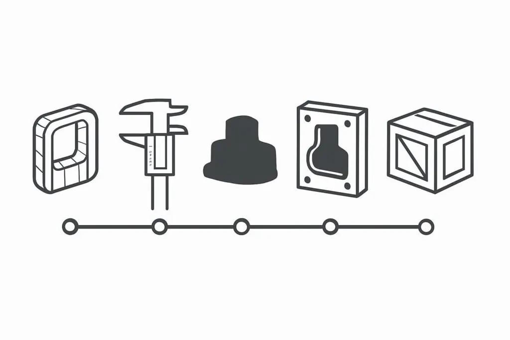
If you’re ready to place an RFQ or start tooling, the fastest path is a process that makes inputs, checkpoints, and acceptance criteria explicit. This guide outlines a practical RFQ-to-shipment workflow for injection molding + tooling—plus where 3D-printed prototypes and contract manufacturing fit.
What this guide covers (and what it doesn’t)
This is a decision-stage workflow. It’s meant for OEM and Tier-1 teams who already know injection molding is the right manufacturing route and now want to minimize surprises.
Covers: rough quote → measurement → 3D-printed prototype confirmation → mold design/build → mold trial (T1) → acceptance → payment and shipment.
Doesn’t cover: detailed DFM guidelines, tolerance capability claims, or legal/commercial terms beyond high-level expectations.
Step 0: What to send for a rough quote
This step is where many RFQs succeed or fail. Plastics Today’s guidance on elements of a strong RFQ reinforces a simple point: quote accuracy improves when the RFQ clearly separates fixed requirements from areas where the supplier can propose options.
Input (from you)
3D CAD (STEP/STP preferred) and any available 2D drawing callouts.
If you don’t have CAD, a physical sample can work for an initial assessment.
Action (what we do)
Review the model/sample for basic manufacturability, complexity drivers, and the likely tooling approach.
Provide a rough quote as a starting point.
Output (what you receive)
A ballpark price and an outline of what assumptions it’s based on.
Done when…
You confirm the rough quote is within range and you want to proceed to measurement + prototype confirmation.
Pro Tip: The biggest reason quotes drift later is missing requirements. Team PTI’s checklist on what to include for an accurate injection molding quote is a useful reference for aligning engineering, quality, and sourcing before you send the RFQ.
If you want a more structured package up front, this RFQ checklist is a good way to ensure nothing critical is left to guesswork.
Step 1: Measurement + 3D-printed prototype (for confirmation of the injection molding RFQ process)
Input (from you)
Approved rough quote.
CAD and/or sample(s) for measurement.
Action (what we do)
Perform measurement and build a reference model for the next steps.
Produce a 3D-printed prototype for fit/assembly confirmation.
Output (what you receive)
Photo/video evidence of the prototype, and (when applicable) a physical prototype for your internal validation.
Done when…
You confirm via photos/videos (and/or receiving the prototype) that the geometry, envelope, and key interfaces are correct.
Key Takeaway: A prototype stage is most valuable when it verifies the assembly reality—clearances, stack-ups, fastening access, and serviceability—not just the appearance.
Step 2: Mold design and mold build (typical 20–60 days)
Input (from you)
Confirmation of the prototype (video/photo sign-off).
Any final notes that affect mold design: cosmetic surface priority, gate vestige preferences, and inspection/acceptance expectations.
Action (what we do)
Complete mold design and begin mold manufacturing.
Build the tool to support stable production, not just first-shot success.
Output (what you receive)
A production-ready mold and a planned trial/sampling step.
Done when…
The mold is completed and ready for the first trial.
What drives the 20–60 day range (injection mold lead time)
“Lead time” isn’t one activity—it’s a chain. In most projects, elapsed time expands because of (a) complexity in the tool itself, and (b) iteration loops after first shots.
At a high level, lead time typically includes:
Feasibility/DFM alignment and mold design decisions (gating, cooling, ejection, side actions)
Tool fabrication and finishing (machining/EDM, fitting, polishing/texture)
Trial (T1) sampling and measurement
Corrections and re-tryout if required
For a neutral overview of how stages and complexity affect timelines, see Aprios’ note on what drives injection molding lead time.
Step 3: Trial mold (T1), inspection, and acceptance
Input (from you)
Your acceptance criteria: which dimensions are critical, how parts will be inspected, and what “pass” looks like.
Action (what we do)
Run a trial mold (T1).
Measure key dimensions and confirm the part meets the defined requirements.
Output (what you receive)
T1 sample parts and inspection results for review.
Done when…
You confirm acceptance of the T1 sample(s) and approve the part for the next step.
⚠️ Warning: The fastest way to add weeks is to discover late that a “nice-to-have” tolerance was treated as “must-hit everywhere.” If only a few interfaces are critical, call those out explicitly.
Step 4: Final payment and shipment (contract manufacturing, prototype to production)
Input (from you)
Acceptance confirmation.
Payment completion per agreed terms (either final payment after trial acceptance, or full prepayment).
Action (what we do)
Prepare parts for shipment and coordinate logistics.
If your program includes downstream operations (assembly, packaging, labeling), align those steps and checkpoints.
Output (what you receive)
Shipped product per the confirmed acceptance state.
Done when…
Shipment is dispatched with the agreed documentation.
If your project is structured as contract manufacturing, payment terms can often be structured more flexibly than a simple “tooling + parts” transaction—especially when the cooperation model and scope (production + assembly/packaging) are clearly defined.
The most common reasons projects slow down (and how to prevent them)
Most schedule slips are preventable. The pattern is usually one of these:
Incomplete RFQ inputs (no clear material grade, no critical tolerances, unclear volume)
Fix: build a requirements pack before RFQ submission.
Late changes after prototype approval
Fix: treat prototype sign-off as a design freeze checkpoint.
Slow confirmation loops (photos/videos, samples, acceptance)
Fix: pre-assign an approver on your side (engineering + quality) and set a review SLA.
Unclear acceptance criteria for T1
Fix: define the “inspection list” up front (critical dimensions, cosmetic zones, functional checks).
If you want a structured way to build that pack and align internal stakeholders, this internal resource may help: build a requirements pack before you contact injection molding companies.
Next step: send CAD (or a sample) for a rough quote
If you’re ready to start, send either:
a 3D CAD file (STEP/STP preferred) plus any critical 2D callouts, or
a physical sample for measurement.
We’ll return a rough quote and confirm the workflow checkpoints before moving into measurement, prototyping, and tooling.