
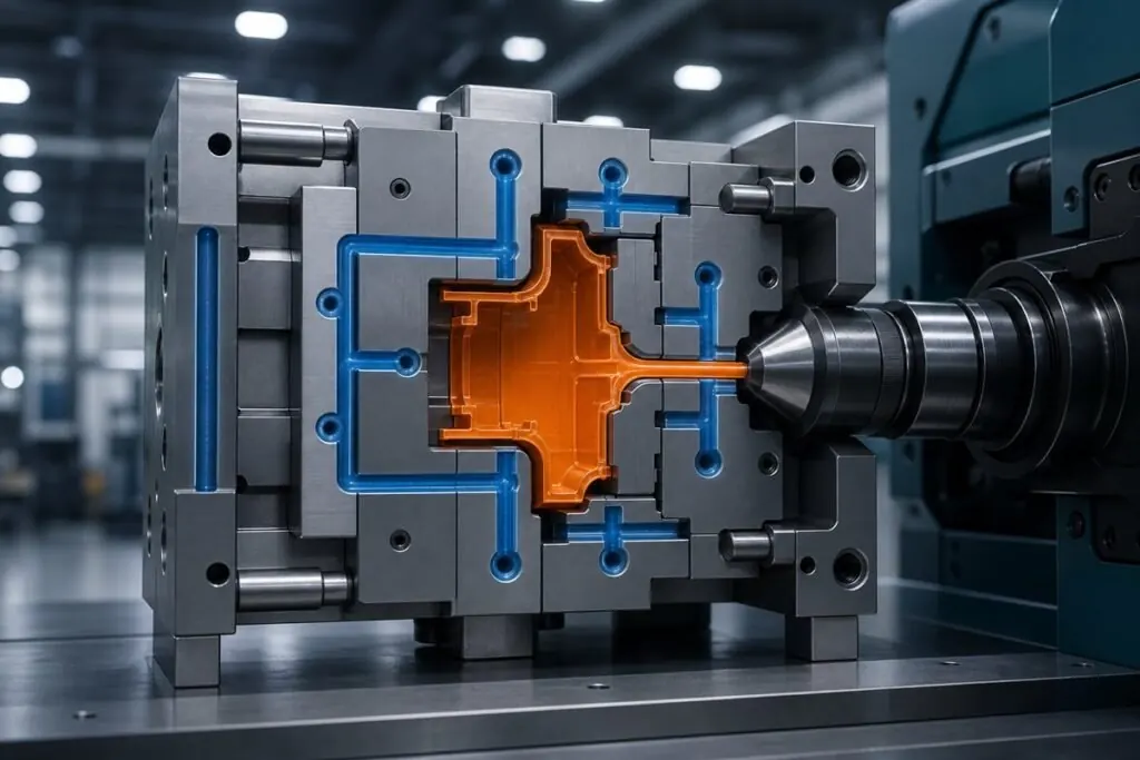
If you are trying to shorten an injection molding cycle, the machine can only move so fast. In most production tools, cooling time is the longest stage—and often the real limit on throughput, dimensional stability, and cosmetic quality.
Injection and clamp actions can be optimized in seconds. But if the plastic has not cooled enough to survive ejection, faster machine motion does not create good parts. It creates deformation, ejector marks, scuffs, and drifting dimensions.
This article explains why injection molding cooling time frequently sets cycle efficiency, what drives it in the mold and in the part design, and how OEM teams can improve productivity without raising scrap.
Cooling is active heat management—not idle waiting
After fill and pack/hold, molten plastic must transfer heat through the mold steel and into the cooling circuit before the part is stable enough to eject. That process usually accounts for more than half of the total cycle in many tools.
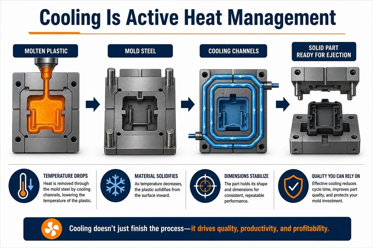
Cooling accomplishes three things at once:
- Heat moves from the melt into the mold and cooling channels, so temperature drops.
- The material solidifies enough to withstand ejection force and downstream handling.
- In-mold dimensions and shape stabilize—directly affecting final quality.
Skip or shorten that work artificially, and the rest of the cycle becomes cosmetic. For a practical overview of where cooling sits in the full sequence, see Deuchi Plastic’s guide: What is plastic injection molding?
Why injection can be fast but the cycle still cannot
Fill time is only a fraction of the shot. A modern press can inject quickly, but ejection timing depends on solidification, not on how fast the machine toggles between phases.
If a part is ejected before it is cool enough:
- Walls may collapse or warp under ejector load.
- Cosmetic surfaces can scuff, whiten, or show stress marks.
- Critical dimensions may drift until the part finishes cooling outside the mold.
Pro Tip: When reviewing cycle time with a molder, ask which feature or wall section sets the cooling time. The answer should be specific—not “we’ll tune it on the floor.”
The thickest section sets the pace for the whole mold
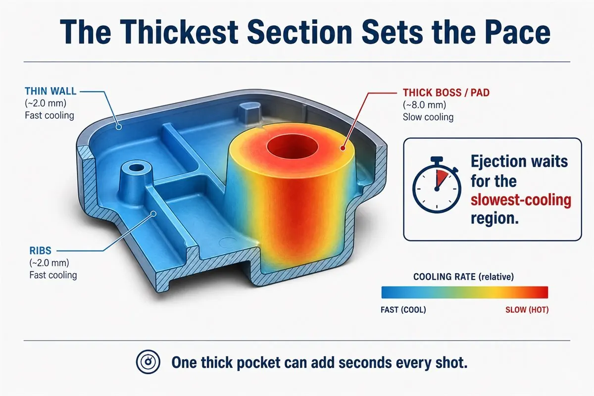
Thin-wall areas may reach ejection temperature early. A local thick section—boss root, rib base, solid pad, or lens core—can still be hot in the center.
The mold cycle must wait for the slowest-cooling region. One thick pocket can add several seconds per shot. At hundreds of shots per day, that is real lost capacity.
This is why “uniform wall thickness” shows up in almost every DFM review. It is not only a strength question. It is a productivity question.
Wall thickness changes the heat path—and the cycle
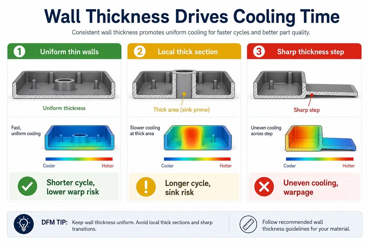
As wall thickness increases, the path for heat to reach the mold wall gets longer, so cooling time rises non-linearly in many geometries.
- Uniform thin walls: shorter cycles, lower warp risk.
- Local thick sections: longer cycles, higher sink risk.
- Sharp thickness transitions: uneven cooling, shrink differences, warpage.
A “small” thickening decision in CAD can become a few extra seconds every cycle in production. Over a year, that cost exceeds the savings from skipping a proper DFM pass.
Deuchi Plastic’s mold design basics for RFQ-ready tools covers how wall transitions, ribs, and bosses affect tooling and process stability.
Uneven cooling drives warpage—not just “bad material”
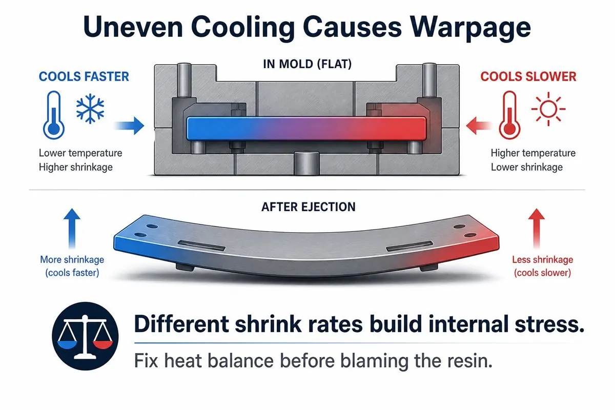
When two sides of a part cool at different rates, shrinkage differs and residual stress builds inside the part. After ejection, that stress releases as bending or twist.
What looks like a cosmetic warp on an enclosure or cover is often a heat-balance problem:
- Different shrink speeds on opposite surfaces.
- Internal stress pulling the part toward the side that cooled faster.
- Both appearance and assembly dimensions affected at the same time.
Before changing resin, verify cooling balance, gate location, and whether thick features sit behind cosmetic surfaces.
Cooling channels are not a mold detail—they are the process
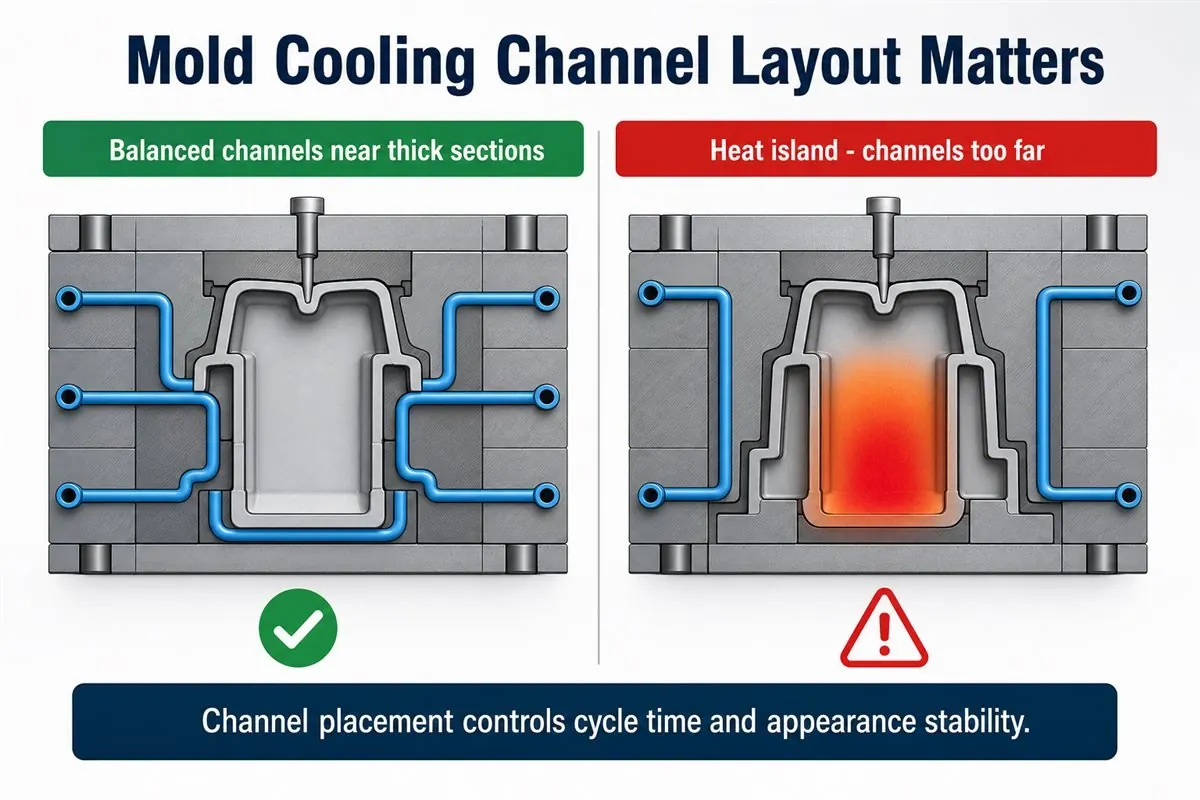
Channel layout determines whether heat leaves the cavity evenly. Channels placed too far from thick sections create heat islands: local hot zones that extend cycle time and destabilize appearance shot to shot.
Good cooling design should:
- Move heat absorbed by the mold into the cooling circuit efficiently.
- Place channels near thick-section hot spots.
- Balance layout so all regions reach safe ejection temperature together.
Advanced tools may use conformal cooling—channels that follow part contours more closely than straight drilled lines—to improve coverage in complex regions. Whether that is justified depends on part geometry, volume, and quality requirements.
Wrong way vs. right way to shorten cooling time
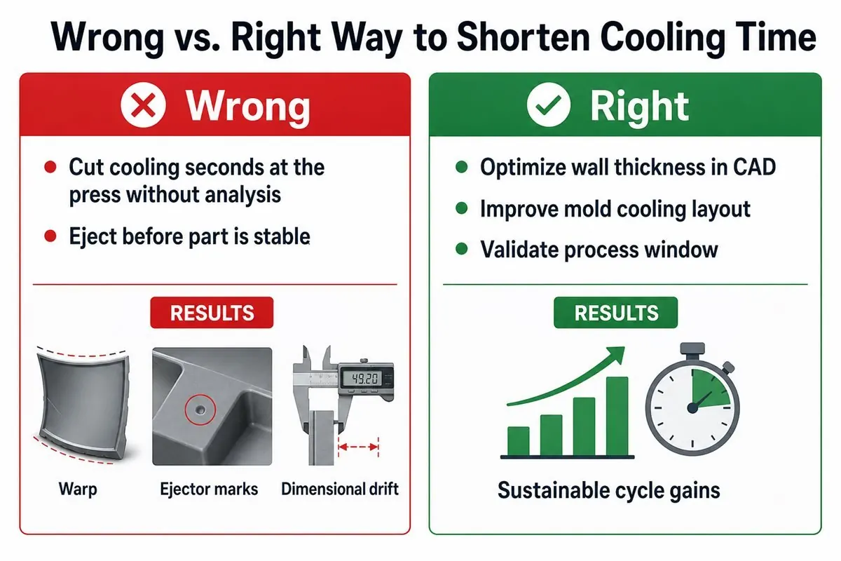
Wrong approach
Simply reducing cooling seconds at the press without engineering analysis. The part may leave the mold before it is stable, increasing deformation, ejector whitening, and dimensional drift—often raising scrap faster than it saves time.
Right approach
Optimize from design and tooling together:
- Reduce unnecessary thick sections and sharp thickness steps.
- Select materials with suitable thermal behavior for the geometry (when spec allows).
- Improve cooling channel placement and balance in the mold.
- Use structural design to avoid heat concentration behind cosmetic surfaces.
Raising mold or melt temperature can change the cooling curve and surface appearance. Any parameter move should follow thermal logic—not trial-and-error at the machine.
⚠️ Warning: A supplier who promises shorter cycles only by “turning down cooling time” without a DFM or mold-cooling plan is trading scrap for speed.
DFM actions you can take at the design stage
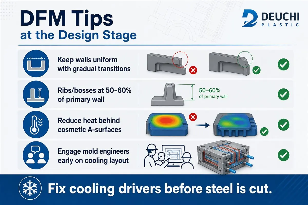
Many cooling problems are cheapest to fix before steel is cut:
- Keep walls uniform and use gradual transitions instead of step changes.
- Limit rib and boss thickness to roughly 50–60% of the primary wall (application dependent).
- Reduce heat behind A-surfaces to lower sink and warp risk on visible faces.
- Engage mold engineers early on cooling layout and ejection strategy.
If you are preparing an RFQ, a focused DFM review can flag thickness drivers and ejection risk before tooling budget is committed. Learn more about Deuchi Plastic’s DFM services.
FAQ: Injection molding cooling time and cycle efficiency
What percentage of the injection molding cycle is cooling?
In many production molds, cooling is the longest phase and often exceeds 50% of total cycle time. The exact share depends on part thickness, material, mold temperature control, and cooling circuit design.
Can I reduce cooling time on the machine to improve productivity?
Only within a validated process window. Cutting cooling without confirming part stability usually increases warp, ejector damage, and dimensional variation. Sustainable gains come from part design, mold cooling, and material selection—not from forcing shorter timers.
Why does one thick section slow the entire mold?
Ejection must wait until every critical region is solid enough. The slowest-cooling thick area becomes the bottleneck for the whole shot, even if thinner sections are ready earlier.
Does uneven cooling always mean the wrong plastic?
Not necessarily. Warp and shrink differences often trace back to thickness variation, gate location, or imbalanced cooling channels before they trace back to resin grade.
When should an OEM involve the molder in cooling strategy?
Before finalizing part geometry for production tooling. Early collaboration on wall thickness, boss/rib design, and mold cooling layout prevents expensive cycle-time and quality problems later.
Next steps
If cooling time or warp risk is showing up in your program, send a requirements pack with CAD, material candidates, target volumes, and critical-to-quality dimensions. Deuchi Plastic can review manufacturability and highlight thickness, cooling, and ejection drivers before you lock the tool design.
Request a quote or email info@deuchiplastic.com.
Published by the Deuchi Plastic engineering team. Deuchi Plastic is a custom injection molding manufacturer in Yueqing, Zhejiang, China, supporting global OEM programs from DFM through production.
See also: contract manufacturing; TPE Overmolding for OEM Parts; Thin Wall Injection Molding for OEM Parts.