
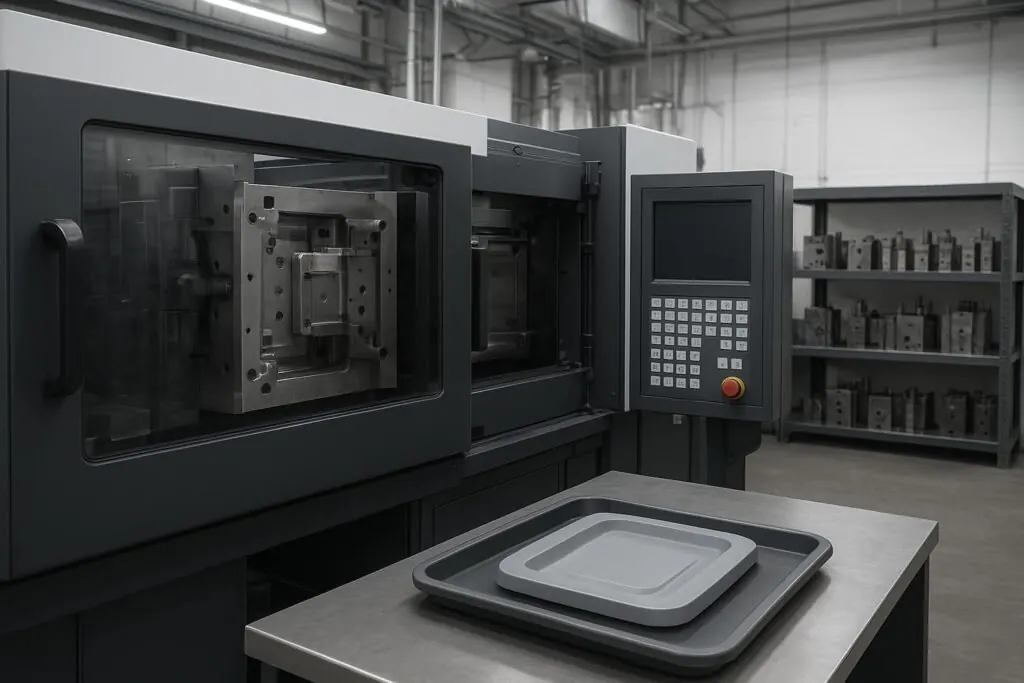
Plastic injection molding is a manufacturing process for making repeatable plastic parts at scale. Plastic pellets are melted, then injected under pressure into a metal mold. The plastic cools in the mold, solidifies, and the part is ejected.
For industrial OEM teams, the value is repeatability: once the tool and process window are proven, you can make the same geometry over and over with controlled variation.
A practical definition (and why engineers care)
The Hubs injection molding guide describes injection molding as a mass-production method where molten polymer is injected into a mold and cooled to form identical parts.
In practice, most engineering and sourcing discussions come back to three questions:
Can the process hold the critical-to-quality (CTQ) dimensions consistently?
What drives unit cost and schedule (cycle time, cavities, scrap, secondary ops)?
How will we validate the tool and lock in change control?
Plastic injection molding process (one cycle)
A molding cycle is the repeatable sequence the machine and mold run to create one “shot” (one part per cavity). At a high level:
1) Clamp
The mold closes and the machine applies clamping force to keep the tool shut against injection pressure.
2) Inject (fill)
Molten plastic is injected into the cavity. The goal is to fill before the flow freezes off.
3) Pack/hold
After fill, the machine holds pressure for a defined time to compensate for shrinkage as the plastic cools. This step often separates stable parts from sink-prone parts.
4) Cool
Cooling is frequently the longest part of the cycle and a major driver of injection molding cycle time.
5) Open and eject
The mold opens and ejector pins (or other ejection features) push the part out.
Pro Tip: When you’re qualifying a supplier, ask how they define and monitor the process window for your CTQs. You want specifics: which parameters are controlled, what their sampling plan looks like, and what happens when the process drifts.
Key terms you’ll see in DFM and tooling discussions
Mold, cavity, and core
Mold: The tool (often steel or aluminum) that forms the part.
Cavity: The side that forms the outside surfaces.
Core: The side that forms internal features like holes, bosses, or internal geometry.
Sprue, runner, and gate
These describe how material enters the part:
Sprue: The main inlet from the machine nozzle into the mold.
Runner: Channels that distribute material from the sprue to one or more cavities.
Gate: The final opening where plastic enters the cavity.
If you’re visualizing the flow path: nozzle → sprue → runner → gate → cavity.
What controls quality in injection molding (high level)
Quality problems usually trace back to a small set of controllable factors.
Material + melt temperature
Resin choice and melt temperature affect flow, packing behavior, and shrink. For some materials, drying and handling are the difference between consistent parts and inconsistent ones.
Pressure + time (fill, pack, hold)
Pressure and time settings are how you fill the cavity and then control shrinkage. If a part is sensitive to sinks, voids, or dimensional drift, packing/holding strategy is often part of the fix.
Cooling + mold temperature control
Cooling is where dimensional stability and productivity collide. Mold temperature control and cooling design affect warpage risk and repeatability.
Tooling and part geometry
Even a well-run press can’t override bad boundaries. Wall thickness transitions, draft, ribs, bosses, and gate location influence flow, shrink, and ejection risk.
If you’re early in design, Deuchi Plastic’s DFM process is aimed at finding these manufacturability risks before they become tooling changes.
When injection molding is a good fit (and when it isn’t)
Injection molding is often the right answer for production parts, but it’s not always the right first step.
Good fit
Injection molding is typically a strong fit when:
Volumes justify tooling.
The design is stable enough that major geometry changes are unlikely.
Repeatability and consistent quality matter more than one-off flexibility.
Protolabs summarizes the advantages and disadvantages of injection molding (2023) with the usual constraints: tooling cost, lead time, and design changes.
Not a great fit
Consider alternatives when:
You need very low quantities or fast iteration.
You’re still learning the design (fit, function, assembly stack-up).
The cost of a tooling change is a major program risk.
A good boundary reference is injection molding vs machining: Xometry’s overview of CNC machining vs plastic injection molding explains why low-volume work often starts with machining.
If you’re still in early validation, injection molding vs 3D printing is usually the real decision: print for speed and learning, mold when geometry and requirements are stable.
Deuchi’s Prototyping services (3D printing, CNC, prototype molds) are designed to support that transition without committing to production tooling too early.
What OEM teams typically want before approving production
For regulated or high-reliability programs, “molding readiness” usually includes first-article measurement and a documentation package that demonstrates the process can run consistently.
Protolabs’ explanation of what PPAP is in manufacturing (2025) is a useful high-level starting point. In plain terms, the buyer wants evidence that the tool, process settings, inspection plan, and change control are defined before release.
If you’re evaluating partners, Deuchi Plastic’s framework on how to choose an injection molding company is a practical checklist of what to ask about DFM depth, tooling strategy, and quality controls.
Next steps
If a part looks like a fit for plastic injection molding, the fastest way to reduce risk is to assemble a requirements pack (CAD, resin candidates, target volumes, CTQs, cosmetic expectations) and run a focused DFM review before tooling.