
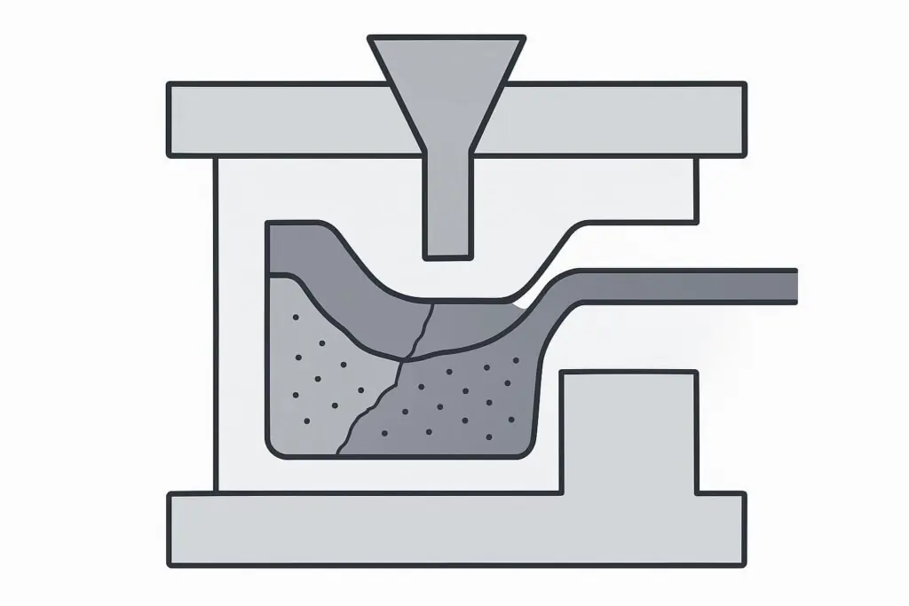
BMC (bulk molding compound) injection molding defects can be frustrating because they often look like “one problem,” but come from two very different mechanisms:
Cracking is usually about cure uniformity + shrinkage stress + ejection stress.
Surface pinholes/porosity (often described on the shop floor as “sand holes”) is usually about trapped gas/volatiles + venting + how the compound is plasticized.
This article is written for troubleshooting—how to compare likely causes, what to check first, and which adjustments tend to help without creating new problems.
If you’re new to where BMC sits in the material landscape (thermosets vs thermoplastics), Deuchi Plastic’s material selection guide gives a quick orientation.
Start with the two questions that narrow the root cause
Before changing settings, answer these two questions. They prevent the common failure mode of “turning knobs” in circles.
When does the defect appear?
At ejection / within minutes → likely under-cure, sticking, or high ejection stress.
Hours to days later → likely residual stress, cure gradients, or post-cure/aging effects.
Where does it appear?
Corners, sharp radii, thickness transitions → shrinkage mismatch + stress concentration.
At ejector pins/parting line witness areas → ejection stress/sticking.
Random surface peppering (tiny pits) → gas/volatiles + venting.
Pro Tip: Take 3 photos per trial—(1) overall part, (2) close-up of the defect, (3) the matching feature in the tool. “Location” is a diagnostic signal.
BMC injection molding defects: cracking (mechanisms that matter)
BMC is a thermoset: once the crosslinking reaction advances, the material can’t simply “re-melt and relax” the way many thermoplastics can. That’s why temperature uniformity and cure completion show up so often in cracking cases.
Mechanism 1: bmc injection molding cracking from uneven cure and shrinkage stress
A classic pattern is a part that contacts colder steel locally (or sees uneven heating across cavities), so the surface cures and locks in earlier while the interior continues reacting. When the interior later shrinks, it’s constrained by the already-set skin.
A practical way to think about it:
Uniform cure → the whole cross-section “sets” together and shrinkage is more consistent.
Gradient cure → different layers want to shrink at different times → stress builds.
Typical mold temperature window (starting point): Many process references put BMC mold temperatures around 130–160°C, with a broader practical range 110–170°C depending on formulation, part thickness, and required cure speed—see SUASE’s thermoset mold temperature table (2025) and IncomePultrusion’s BMC mold temperature range (2025). Use these as a starting window, then validate against your compound supplier’s data.
What to check first (fast checks):
Mold temperature uniformity (multiple points, not one thermocouple).
Cure time consistency (actual time-at-temperature).
Whether cracks correlate with a specific cavity, insert, or steel mass difference.
What usually helps:
Raise mold temperature within the compound window and improve uniformity across the tool.
Adjust cure time so the part has enough hot strength before ejection.
Mechanism 2: under-cure vs over-cure (both can crack)
Cracking is often described as “not cured enough,” but over-cure can also create brittle behavior or shrinkage stress.
Use symptom signals to separate them:
Under-cure signals: soft or tacky surface, low hot strength, cracks during ejection/trim, inconsistent mechanical performance.
Over-cure signals: excessive brittleness, discoloration/darkening, increased internal stress, cracks that seem to originate at stress concentrators, even with gentle handling.
Because cure behavior is compound-specific, the safest troubleshooting approach is to change one variable at a time and record it.
Mechanism 3: ejection stress and stress concentrators (corners, pins, draft)
Even with a good cure, a part can crack if it has to fight the tool to come out.
Common triggers:
Sharp internal corners or minimal radii
Thick-to-thin transitions
Undercuts or insufficient draft
Sticking to the core leading to “snap” release
Ejector pin pattern that loads one region heavily
A useful general reference on crack patterns and corner stress is Paulson Training’s overview of cracks in molded parts (2012). The thermoset-specific takeaway is simple: don’t rely on ductility to save you—design and ejection need to be right.
If cracking keeps tracking to geometry features (radii, transitions, knit lines), a DFM review is usually higher leverage than another parameter tweak.
BMC molding porosity (“sand holes”) and pinholes: what’s really happening
If the surface looks like it’s peppered with tiny pits, think first about gas:
Air trapped in the cavity
Volatiles released during heat-up/cure (moisture, release agent, other volatiles)
Gas is created when the flow front “folds” or hesitates and traps air pockets
Mechanism 1: Mold venting is insufficient where gas actually traps
Venting is not just “put vents on the parting line.” The vents have to be where the gas wants to go: last-to-fill zones and features that create pockets.
Bosses, ribs, and deep pockets are repeat offenders. A practical venting discussion with shop-floor detail is Randy Kerkstra’s article, “Venting of Mold Components” in MoldMaking Technology (2015).
What to check first:
Are the vents clean and open (not polished shut, not clogged)?
Do you have venting at likely gas-trap features (bosses/ribs) rather than only at the perimeter?
Does porosity cluster in the same locations each time? If yes, venting/location is your clue.
Mechanism 2: moisture/volatiles in the compound become gas during cure
BMC formulations can be sensitive to storage and handling. Moisture or excess volatiles don’t always show up as a dramatic blister—often it’s subtle surface porosity.
What to check:
Storage conditions, open time, and whether the material was warmed/conditioned consistently.
Lot-to-lot changes.
Whether defects spike on humid days or after extended exposure.
Mechanism 3: plasticizing stage—screw speed, back pressure, and fiber condition
In BMC injection, how you prepare the shot can make or break surface quality.
Why screw speed matters:
Too high can increase shear.
For BMC (glass + fillers), excessive shear can contribute to fiber breakage and non-uniform fiber distribution.
It can also increase air entrainment, depending on feeding and recovery behavior.
Why back pressure matters:
Back pressure helps compact and densify the compound during recovery, which can reduce entrained air and stabilize shot consistency.
Too low can leave the shot “fluffy” (more prone to voids and surface porosity).
Too high can over-shear the compound and create other issues.
A reasonable, safe way to apply your knob-turning rule:
If you see pinholes/porosity, reduce screw speed and increase back pressure moderately to densify the shot.
Then re-check venting and material condition; don’t use plasticizing changes to compensate for a venting problem.
⚠️ Warning: Avoid “hero” adjustments. Big jumps in mold temperature, cure time, or back pressure can fix one defect and create another (flash, sticking, surface scum, fiber damage). Move in controlled steps and document each trial.
Troubleshooting table: symptom → likely causes → checks → actions
Use this as a structured comparison, not a list of random fixes.
Symptom pattern | Most likely cause family | What to check (fast) | What to change first |
|---|---|---|---|
Cracks at ejection, near pins, or parts stick, then crack | Under-cure or high ejection stress | Cure time-at-temp, mold temp uniformity, draft, pin layout, release | Increase cure time or mold temp within window; reduce ejection shock; improve draft/pin support |
Corner cracks or cracks at thickness transitions | Shrinkage mismatch + stress concentration | Radii, transitions, local steel temperature, and core locking | Improve radii/transition via DFM; balance mold temperature; avoid over-packing |
Cracks that appear hours/days later | Residual stress/cure gradient | Mold temp mapping, cavity-to-cavity variation, post-cure history | Improve temperature uniformity; validate cure schedule; consider controlled post-cure if supplier recommends |
Pinholes/peppering in repeatable surface zones | Trapped gas + poor venting location | Vent presence/cleanliness at last-to-fill; gas trap features | Clean/open vents; add venting where gas traps (bosses/ribs); adjust fill pattern if possible |
Pinholes increase with higher screw speed | Air entrainment / shear / fiber damage | Recovery behavior, shot consistency, surface texture vs flow direction | Lower screw speed; add moderate back pressure; verify material feed stability |
Random porosity across large surfaces | Material volatiles/moisture + inadequate degassing | Storage/open time, humidity, lot changes | Tighten material handling; validate conditioning; then revisit venting and plasticizing |
A short checklist for the next trial
Keep this checklist tight; it’s meant to be actionable.
Record defect when + where (ejection? later? corners? pins? last-to-fill zones?).
Verify mold temperature across multiple points; target uniformity first, not just “higher.”
Confirm cure time-at-temperature is consistent and adequate for the compound.
Inspect vents for clogging/polish shut; confirm venting at likely gas traps.
If pinholes persist: reduce screw speed and increase back pressure moderately to densify the shot.
If cracking persists at geometry features: pause parameter tweaks and run a focused DFM review on radii, transitions, draft, and ejection support.
When to stop tweaking and review the tool and part design
If you’ve made controlled changes to mold temperature uniformity, cure time, vent cleanliness, and plasticizing settings and the defect location stays the same, you’re likely dealing with:
a persistent gas-trap feature that needs venting changes,
a geometry-driven stress concentrator,
a local hot/cold spot caused by steel mass or heater layout,
or an ejection/support layout issue.
That’s usually a mold-build/process-control question, not a “try one more setting” question. Deuchi Plastic’s mold build overview and its RFQ process guide are good references for what data to provide when you need a supplier to troubleshoot with you.
Next steps (if you want a second set of eyes)
If you’re working through BMC injection molding defects and want a structured review, Deuchi Plastic can help by:
reviewing your defect photos + trial notes,
checking whether geometry is driving cracking risk (via DFM),
and evaluating whether venting and tool details are likely to be trapping gas (see Mold Build).
If you’re also qualifying a new supplier or transferring tools, the supplier-qualification checklist in Injection molding OEM qualification is a practical place to start.