
OEMs specifying insert molding contract manufacturing need more than a press and a bin of brass nuts. Metal inserts change heat balance, flow fronts, ejection stress, and tolerance stacks. Programs fail when DFM treats the plastic body in isolation and ignores insert placement, retention features, and secondary operations.
Insert molding places pre-formed components — threaded inserts, bushings, stamped contacts, magnets, or PCB stubs — into the cavity before the shot, then encapsulates them. Done well, it eliminates post-mold assembly steps and improves pull-out strength. Done poorly, it creates short shots, flash into threads, cracked bosses, and scrap cascades that destroy piece-price savings.
This guide covers process fundamentals, DFM for insert placement, tolerance and retention, secondary ops realities, and what OEM RFQs must include so quotes and molds are built for the full process — not the plastic-only subset.
Process overview: what insert molding actually includes
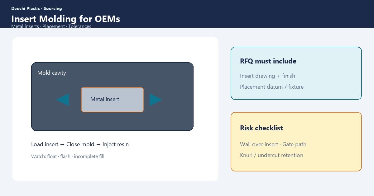
A robust insert molding cell combines insert preparation, loading accuracy, molding, and verification. Loading may be manual, pick-and-place, or overmolded on a rotary table depending on volume and insert geometry.
- Insert preparation — cleaning, plating integrity check, preheating when required for dimensional and bonding stability
- Fixturing / loading — locators that hold insert height, rotation, and concentricity through clamp
- Shot and pack — fill without displacing inserts; avoid high shear that washes plating or knurl
- Ejection — protect threads and thin walls; sequence so inserts do not pull out of plastic or vice versa
- Inspection — presence checks, pull-out sampling, thread gauges, electrical continuity when relevant
Contract manufacturers should quote the integrated process. A molded body price that excludes insert cost, loading labor, scrap yield, and gauging understates TCO — see total cost ownership.
Cycle time math must include load and unload. A 25-second plastic fill and cool can become a 45-second process when operators seat four threaded inserts by hand. Automation pays when volume and insert consistency justify fixtures — document that assumption in the RFQ so piece price comparisons stay honest.
Metal insert types and retention design
| Insert type | Typical use | DFM focus |
|---|---|---|
| Brass threaded insert | Fastener bosses in housings | Knurl geometry, embed depth, sink opposite boss |
| Steel bushing / pin | Wear or alignment features | Concentricity, press fit vs overmold retention |
| Stamped contact / terminal | Electrical interconnect | Flash into contact zone, plating wash |
| Magnet / powdered metal | Sensors, latches | Field orientation, brittle insert handling |
| Threaded standoff | PCB mounts in enclosures | Height stack, warpage of plate |
Retention is a plastic design problem: undercuts on knurls, flanges that resist pull-out, and enough plastic section to carry load without cracking. Undersized bosses around high-strength inserts crack under torque. Oversized masses sink and warp.
Specify assembly torque and expected rework cycles on threaded inserts. A boss that survives one installation may crack on field service if the plastic section and embed depth were sized only for first assembly. Pull-out and torque-to-strip tests belong in the quality plan with sample sizes stated up front.
DFM for insert placement and gate strategy
Insert location interacts with gate position, weld lines, and cooling. Plastic should flow around the insert without leaving knit lines in structural sections, without washing the insert off its locator, and without trapping air against flat insert faces.
- Place gates so flow balances around inserts rather than pushing them off-center
- Provide venting paths where plastic meets large flat insert faces
- Maintain wall uniformity adjacent to inserts to control shrink and sink
- Add draft and radii so ejection does not shear plastic from the insert interface
- Design shut-offs that protect threads and terminal zones from flash
- Confirm insert preload fixtures do not block cooling channels in steel
Run DFM with both plastic and insert STLs (or equivalent). Our DFM checklist and DFM services treat insert molding as a coupled system — not a molded blank with “inserts later.”
Tolerance, CTQs, and measurement
Insert molding CTQs often include insert height relative to a plastic datum, concentricity to a bore, thread true-position, and plastic wall around the insert. Specifying ±0.05 mm on every feature forces scrap without clarifying which dimensions actually matter to function.
| CTQ class | Example | Measurement approach |
|---|---|---|
| Functional stack | Insert height to mating plane | Fixture + height gauge / CMM |
| Retention | Pull-out or torque-to-fail | Destructive sampling plan |
| Cosmetic | Witness lines around bosses | Defined light and acceptance photos |
| Electrical | Continuity / insulation | Hi-pot or continuity fixtures |
| Thread integrity | Go/no-go after mold | Thread gauges; flash inspection |
Include FAI expectations early. Insert presence and flash into threads are launch killers — align inspection with our first article inspection guide.
For multi-cavity insert tools, correlate insert height and true position cavity-by-cavity. A single golden cavity that passes FAI does not prove the family. Imbalance in filling or uneven steel temperatures will show first as insert float and flash variation — not as an obvious short shot.
Secondary operations and yield realities
Even “complete” insert molding often needs secondary work: thread chasing after occasional flash, degating, ultrasonic welding of lids, pad printing, or assembly into next-level fixtures. Quote these explicitly. Yield on insert presence checks at volume can dominate labor cost if loading fixtures are weak.
- Define insert supplier and incoming inspection criteria (plating, dimension, contamination)
- Specify whether inserts are customer-furnished or manufacturer-procured
- Agree scrap ownership when insert cost is significant relative to plastic
- Plan lot traceability for both resin and insert lots
- Decide in-cavity vs post-mold installation when volumes or geometries force a split
Post-mold thermal inserts remain valid for low volume. Do not force cavity insert molding when bridge volumes cannot justify fixtures — map the path using the prototype-to-production roadmap.
OEM RFQ checklist for insert molding
- Plastic CAD + insert CAD with mating datums and revision control
- Insert material, plating, and approved vendor list if constrained
- Retention requirements (pull-out force, torque) with test method
- Annual volume and expected inserts per shot / cavity layout concepts
- Cosmetic class around boss areas and acceptance photos if available
- Electrical or sealing requirements after overmold
- Preferred ownership of insert inventory and safety-stock policy
Incomplete RFQs produce plastic-only quotes that ignore the real process. For enclosure-heavy insert programs, also see electrical enclosure contract manufacturing.
How Deuchi approaches insert molding
Deuchi integrates insert strategy into mold build and production planning — locators, shut-offs, and inspection fixtures belong in the quote narrative. We prefer written DFM callouts on displacement risk, sink opposite inserts, and thread protection before steel release.
Contract manufacturing scope can include insert procurement coordination, molding, and defined secondary ops under one program manager so yield and CTQs stay visible.
FAQ
When should we use in-mold inserts vs post-mold installation?
Choose in-mold for high retention, higher volumes, and automated loading ROI. Use post-mold thermal or ultrasonic inserts for low volume, frequent design change, or when cavity real estate cannot hold locators cleanly.
Do inserts need preheating?
Often yes for larger metal inserts — temperature matching reduces local sink/stress and can improve dimensional stability. Confirm with material and insert mass; document the process window.
Who should supply the metal inserts?
Either model works if incoming inspection and scrap rules are clear. Manufacturer-procured inserts simplify logistics; customer-furnished inserts protect approved vendors for plating or specialty contacts.
What is the most common production failure mode?
Flash into threads, insert float off locator, and cracking of thin plastic around high-torque bosses. All are DFM/fixture issues more often than “press problems.”
Next step: Contact Deuchi with plastic CAD, insert specs, retention requirements, and volume — we will return DFM and a process-inclusive quote path.