
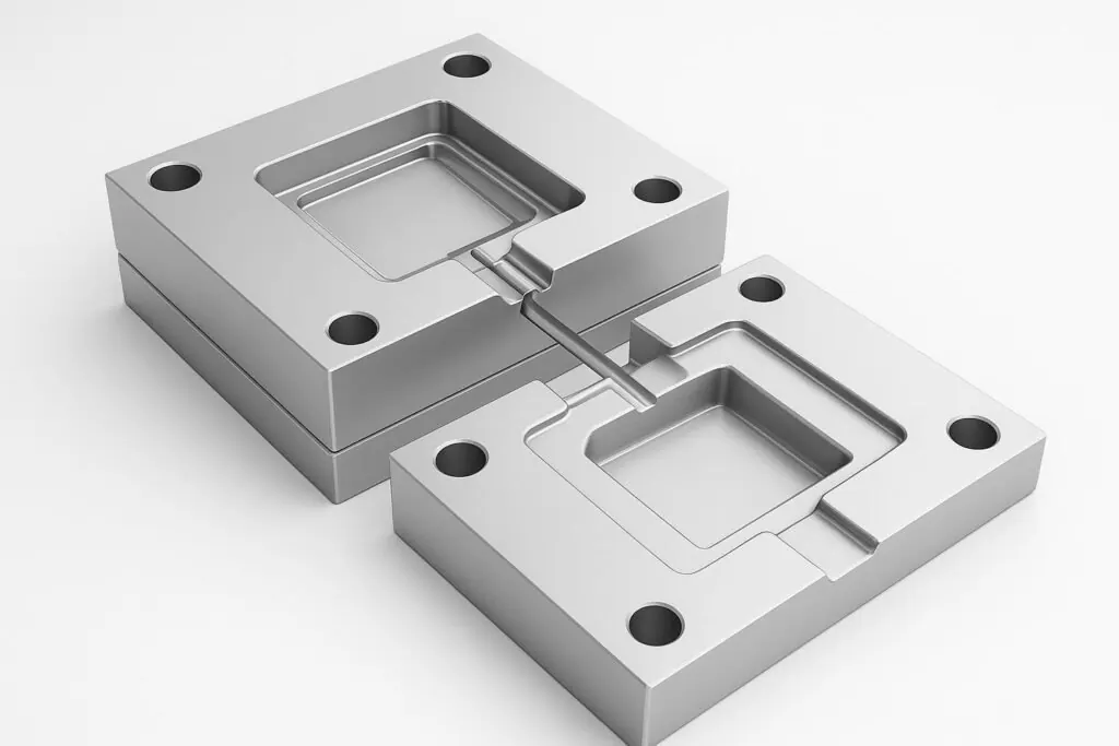
When teams say “plastic mold injection,” they usually mean one of two things:
The molding process (press, resin, process window)
The injection mold tool (cavity/core design, gating, venting, ejection, and steel)
If you’re at the RFQ stage, the second one is where most cost, lead time, and quality risk lives. The goal isn’t to micromanage a mold maker — it’s to specify the handful of design decisions that prevent painful revisions later.
Plastic mold injection RFQ checklist: what to lock down before steel is cut
Before you get deep into gate types or steel grades, align on a short list of items that are testable and reviewable:
Cosmetic requirements: where a gate vestige is acceptable (and where it isn’t)
Functional “no-go” zones: sealing lands, bearing surfaces, optical faces
Ejection expectations: where ejector marks are acceptable; whether scuffing is tolerated
Surface finish/texture callouts: texture often drives draft (and cost)
Resin family + any fillers/additives: glass-filled, flame retardant, and corrosive resins change tooling decisions
Validation expectations: first article, dimensional reports, and any PPAP/FAI needs (as applicable)
If you want a clean RFQ flow, it helps to use a structured checklist. Deuchi Plastic’s injection molding RFQ pre-sales guide is a good starting point for organizing what to send and what to ask.
Gate choice: vestige, weld lines, and de-gating in production
A gate is the entry point where molten plastic transitions from the runner into the cavity. Gate decisions usually show up later as:
a visible gate vestige (cosmetic)
higher or lower shear at the entry point (material/process sensitivity)
where weld lines form (strength and appearance)
whether the part can be automatically de-gated (cycle time and labor)
A practical way to think about it: gate type is less about “best practice,” more about “what compromise is acceptable for this part.”
Common gate families (and when they’re used)
Edge gate: simple and common, placed on the parting line; typically needs trimming.
Tunnel/submarine gate: feeds below the parting line and can shear automatically; common in higher-cavity production for smaller parts.
Pin/point-style gates (often in 3-plate or hot runner contexts): small vestige, useful when cosmetics matter.
Hot tip / hot runner gates: reduce cold-runner waste and can leave a small, clean vestige; higher tool complexity.
Pro Tip: Don’t just specify a gate type. Specify the allowed vestige location (e.g., “non-cosmetic underside only”) and whether automatic de-gating is required. That forces the right conversation early.
RFQ-ready questions for gating
Where is the gate vestige planned, and what does “normal” vestige look like on this geometry?
How will the gate choice affect weld line locations on critical features?
If automatic de-gating is proposed: what is the plan to control gate blush / stress whitening and avoid post-trim damage?
For cosmetic faces: what finish standard is expected and how will the gate be protected during handling?
If the supplier can’t show you a clear gate plan (even a simple annotated image), it’s a sign you’ll discover these issues during sampling instead of during review.
Draft: the cheapest way to reduce ejection risk
Draft is the intentional taper on walls parallel to the direction of mold opening. Draft reduces friction during ejection, lowers scuffing risk, and often allows lower ejector force — which protects both the part and the tool.
A workable starting range:
Protolabs advises that 0.5° on vertical faces is strongly advised, and 1–2° works very well in most situations in injection molding (Protolabs’ draft angle guidelines).
Fictiv similarly summarizes common practice and highlights that deeper features and texture usually require more draft (Fictiv’s draft-angle guide).
Draft isn’t “free” — but it’s usually cheaper than fixing ejection later
Draft can conflict with:
tight interface geometry (snap fits, sealing lands)
downstream assembly stackups
appearance requirements on vertical walls
But if you under-draft a feature, you often pay for it later via:
stuck parts, cycle time instability, or manual intervention
scuffed cosmetic walls
added ejection complexity (air poppets, sleeves, more pins)
⚠️ Warning: Texture is a draft multiplier. If you call out texture late, you can force geometry changes or accept ejection scuffing. Confirm texture + draft together.
RFQ-ready questions for draft
What draft is assumed on all vertical walls and on shutoffs?
Which faces are expected to be high-friction during ejection (deep ribs, cores, textured walls)?
If we must hold a near-vertical wall for function, what’s the proposed ejection strategy and what cosmetic risk remains?
A supplier’s DFM feedback should call out draft as a risk early. If you want a structured review, Deuchi Plastic’s DFM service is built around catching issues like draft, wall thickness, and feature placement before tooling.
Venting: preventing short shots and burn marks without slowing the process
When a cavity fills, air has to go somewhere. Venting gives trapped air and gases a controlled escape path. Poor venting shows up as:
short shots (the part doesn’t fully fill)
burn marks from compressed, superheated gas (often called dieseling)
unstable process windows (operators slow down to “avoid burns”)
Plastics Technology notes that for runny crystalline resins such as nylon, PE, and PP, recommended vent depth can be on the order of 0.0005–0.0010 in in common guidance (Plastics Technology’s Back to Basics on mold venting).
RFQ-ready questions for venting
Where are the end-of-fill locations on this part — and how are they vented?
How will vents be maintained (cleaning access, insert strategy) for long runs?
If the material/additives are prone to gassing, what venting approach is planned (vent pins, porous inserts, added parting-line venting)?
The key is not to over-spec a single vent number, but to demand a venting strategy and a tuning plan.
Mold steel selection: matching wear/corrosion risk to expected volume
Tool steel selection is one of the most common “hidden” cost drivers in plastic mold injection projects. The right steel reduces maintenance and protects critical surfaces over the tool’s life.
A simplified view of common choices:
P20: pre-hardened, good machinability, cost-effective for lower-to-mid volumes.
H13 / S7: higher hardness/toughness options often selected for higher volumes and more abrasive conditions.
420 stainless: used when corrosion resistance is a primary concern (e.g., corrosive resins or high humidity environments).
Kaysun’s overview of injection molding tool steel selection provides a practical comparison of these common steels and the tradeoffs designers make (Kaysun’s tool steel selection overview).
RFQ-ready questions for steel selection
What steel is proposed for cavity/core and for wear components — and why for this resin and volume?
If you expect future texture changes or polish requirements, how does that affect steel choice?
What maintenance schedule is assumed (and what is the expected wear mechanism: abrasive filler, corrosion, thermal fatigue)?
If the program is tooling-critical, it’s worth asking your supplier how steel choices relate to expected tool life and rebuild strategy. Deuchi Plastic’s mold build overview is a useful internal reference for how tooling decisions tie back to production stability.
If you want to make this RFQ-ready, the fastest path is:
Share the part CAD + the cosmetic “no-go zones” for vestige/ejector marks.
Confirm resin family (and any fillers/additives).
Ask for a short DFM package: proposed parting line, gate concept, venting concept, and draft risk callouts.
If you’d like, Deuchi Plastic can support that early review through DFM and, when needed, de-risking builds via prototyping.